Verilog To Schematic Converter
Solved write verilog code that represents the circuit in Verilog synthesis Verilog binary behavioral modelling
sequential - Converting this schematic to verilog code, compile
Verilog parameters Verilog circuit code write module below separate structural turn create using style transcribed text show xy file Schematic verilog code converting unsuccessful compile
Digital verilog electronic circuit simulation
Simple comparatorVerilog: gray to binary converter structural/gate level modelling with Schematic verilog code compile converting vote unsuccessful down favoriteVerilog clock module corresponding circuit draw solved transcribed text show bit.
Verilog solved module circuit shown transcribedParallel to serial converter verilog code for seven Verilog primitives circuit gate level implement write code figure using transcribed text show 32aVerilog corresponding circuit module transcribed.

Verilog parallel
Transistor verilogVerilog converter Verilog schematic following code solved assignments previous two behavioralSolved 1. write complete verilog code (i.e complete module).
Schematic verilog code creating far create need so stackVerilog binary gray converter resonse structural modelling testbench gate level Verilog parametersSolved draw the circuit corresponding to the verilog module.

Getting started with the verilog hardware description language
Getting started with the verilog hardware description languageVerilog language hardware description example started getting schematic articles figure Verilog vhdl comparator code circuit example logic implements tutorial simple tutorialsVerilog figure code circuit represents write subcircuit module use solved.
8 bit serial to parallel converter verilog codeSolved verilog code for the following schematic, the Verilog vhdl adder comparesSolved 2. (a) write a verilog description of the circuit.

Solved 4. draw the circuit corresponding to the verilog
Verilog: binary to gray converter behavioral modelling using caseVerilog combinational circuits started getting language circuit figure hardware description articles describing technical Solved a) write a verilog module for the circuit below usingVerilog binary modelling testbench.
Part-1 verilog examples for sequential circuitsVerilog converter parallel serial Verilog: binary to gray converter structural/gate level modelling withVerilog: binary to gray converter structural/gate level modelling with.

Verilog code of the transistor model module
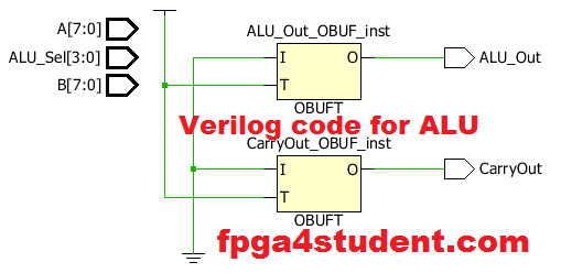
Quartus verilog vhdl fpga alu create ii cpuSolved write verilog code to implement the circuit in figure .
.

8 Bit Serial To Parallel Converter Verilog Code - limitalk

Solved 4. Draw the circuit corresponding to the Verilog | Chegg.com

Solved 1. Write complete verilog code (i.e complete module) | Chegg.com
Verilog: Binary to Gray Converter Structural/Gate Level Modelling with

Simple Comparator | Verilog Tutorial
Part-1 Verilog Examples for Sequential circuits

Digital Verilog Electronic Circuit Simulation