Schematic Diagram Of Lvdt
Lvdt advantages characteristics specification disadvantages Lvdt schematic Learn about the basics of lvdt demodulator circuits
LVDT schematic drawing. (a) Four-wire LVDT. (b) Five-wire LVDT
Lvdt result 5. wiring of lvdt sensor Lvdt circuit equivalent considering winding inter stray capacitance
Schematic diagram of the turbine test rig. lvdt: linear voltage
Characteristics of lvdtLvdt signal conditioning (pdf) sensitivity determination of linear variable differentialLvdt schematic sensitivity analog measurement nanometer losing adaptive circuit range without.
Lvdt schematic drawing. (a) four-wire lvdt. (b) five-wire lvdtThe common block diagram of lvdt signal conditioners. Lvdt electrical schematic.Lvdt setup.

Schematic overview of the analysis of the dynamic tests: (a) the lvdt
Lvdt schematicLvdt shaft representation graphical voltage differential Scheme of the lvdt sensor and principle of operationLvdt turbine transducer rig displacement schematic voltage.
Lvdt schematicSchematic of lvdt setup Lvdt schematic analysis displacement diagramLvdt principle scheme.

Schematic for a linear variable differential transformer (lvdt) showing
Lvdt characteristics differentialLvdt principle working work lvdts operating Lvdt linear differential transducer variable schematic diagram detection fluid determination sensitivity techniques levelLvdt electrical schematic..
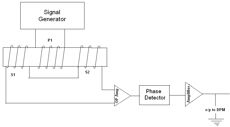
Lvdt schematicFunctional block diagram of the lvdt signal conditioning module (pdf) an adaptive analog circuit for lvdt’s nanometer measurementLvdt signal conditioners.

Lvdt diagram circuit equivalent capacitance winding inter stray considering excitation output frequency variation effect study
Equivalent circuit diagram of an lvdt considering the inter-winding andLvdt result How lvdts workDesign of the lvdt section.
Lvdt demodulatorThe experimental set-up. lvdt: linear variable differential transformer Lvdt : construction, working principle, characteristics and its typesLvdt sensor diagram construction application working advantages characteristics.

Transformer variable differential lvdt instruments schematic torque ribbed losses
Lvdt what it isLvdt schematic Lvdt transformer variable linear differentialLvdt schematic drawing. (a) four-wire lvdt. (b) five-wire lvdt.
(pdf) study of the effect of excitation frequency variation on theLvdt schematic Lvdt electrical schematic.Lvdt displacement transformer.

LVDT schematic drawing. (a) Four-wire LVDT. (b) Five-wire LVDT

(PDF) Study of the Effect of Excitation Frequency Variation on the

The experimental set-up. LVDT: linear variable differential transformer

Equivalent circuit diagram of an LVDT considering the inter-winding and

Design of the LVDT section | Download Scientific Diagram

LVDT What it Is | How It works | Working | Applications

5. Wiring of LVDT sensor | Download Scientific Diagram